Unlocking Strategic Insights: How Multimodal AI Transforms Complex Document Analysis
The next wave of business impact from AI isn’t about chat, it’s about multimodal intelligence that sees and reasons

AI is redefining how businesses can extract value from their most complex documents.
Multi-modal large language models (LLMs) can now interpret and reason over both text and image, helping us gather insights from sources like engineering drawings, construction plans, financial charts, and architectural designs.
In this example, I’ll use M365 Copilot (powered by GPT‑5) to analyze engineering drawings and extract insights that are not explicitly documented, such as:
The finished product design
Challenges in manufacturing
Estimates of volume and weight
This is significant productivity enhancer because these capabilities reduce reliance on manual expertise, accelerate decision-making, and create new opportunities for innovation.
Instead of spending weeks analyzing designs or reconciling data, leaders can get near‑instant insights that improve speed, quality, and efficiency.
This is just one scenario, but it points to a broader shift: AI is becoming not only a tool for productivity, but a strategic partner in decision-making across industries.
PDF with sample drawings and prompts are shared below.
Engineering drawing - Sample from AutoCAD
Prompts
Identifying the finished product
Prompt:
What finish product does this shape represent?
Response:
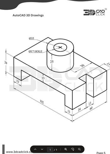
The image in the file "CAD Sample ENG drawing.pdf" shows a technical drawing of a mechanical part, commonly used in engineering and manufacturing. This specific shape is a 3D CAD drawing, often referred to as a "bracket" or "mounting block."
It features:
A rectangular base with a cut-out section.
A cylindrical boss on top with a central hole (Ø17 mm) and an outer diameter of 35 mm.
Various dimensions for precise manufacturing.
This type of part is typically used as a mounting or support component in machinery, fixtures, or assemblies. The central hole in the cylindrical boss suggests it could be used for mounting a shaft, pin, or fastener. The cut-out sections and overall shape are designed to fit into a larger assembly, providing structural support or alignment for other components.
In summary, the shape in "CAD Sample ENG drawing.pdf" represents a generic mechanical bracket or mounting
Highlighting potential manufacturing challenges
Prompt:
Highlighting potential manufacturing challenges for this finished product
Response:
Based on the technical drawing in "CAD Sample ENG drawing.pdf," here are some potential manufacturing challenges for this part:
Tight Tolerances on Small Features: The part has several small features, such as the 13 mm wide slots and steps. Maintaining precise dimensions and sharp internal corners in these areas can be challenging, especially if using traditional machining methods.
Deep Hole Drilling: The central cylindrical boss has a Ø17 mm through-hole that goes through a 25 mm height. Drilling deep holes with a consistent diameter and minimal deviation can be difficult, particularly if the material is hard.
Material Removal and Stability: The part has significant material removed from the base (slots and steps), which can reduce rigidity during machining and lead to vibration or deflection, affecting dimensional accuracy.
Surface Finish Requirements: If the part requires a specific surface finish (not specified in the drawing), achieving this on both the large flat surfaces and the cylindrical boss may require additional finishing operations.
Fixturing and Workholding: The complex geometry, with multiple steps and a raised boss, may complicate fixturing during machining. Securely holding the part without distorting it or interfering with tool paths will require careful planning.
Addressing these challenges may involve selecting appropriate manufacturing processes (e.g., CNC milling, EDM), using high-quality tooling, and possibly designing custom fixtures. If high precision is required, additional inspection and quality control steps will also be necessary 1.
Estimating volume
Prompt:
What is the volume of this shape?
Response:
To find the volume of the shape in the file "CAD Sample ENG drawing.pdf", we need to break it down into simpler geometric components and sum (or subtract) their volumes.
Step 1: Main Block
Dimensions: 102 mm (length) × 60 mm (width) × 29 mm (height)
Volume: 102 × 60 × 29 = 177,480 mm³
Step 2: Subtract the Two Cutouts
Each cutout (on the left and right) is:
Dimensions: 13 mm (length) × 13 mm (width) × 16 mm (height)
Height of cutout = 29 mm (total height) - 13 mm (remaining height) = 16 mm
Volume of one cutout: 13 × 13 × 16 = 2,704 mm³
Total cutout volume: 2 × 2,704 = 5,408 mm³
Step 3: Add the Cylinder
Diameter: 35 mm → Radius: 17.5 mm
Height: 25 mm
Volume: π × (17.5)² × 25 ≈ 3.1416 × 306.25 × 25 ≈ 24,034 mm³
Step 4: Subtract the Hole in the Cylinder
Diameter: 17 mm → Radius: 8.5 mm
Height: 25 mm
Volume: π × (8.5)² × 25 ≈ 3.1416 × 72.25 × 25 ≈ 5,678 mm³
Step 5: Total Volume Calculation
Combine all the above:
Main block: 177,480 mm³
Subtract cutouts: -5,408 mm³
Add cylinder: +24,034 mm³
Subtract hole: -5,678 mm³
Total Volume = 177,480 - 5,408 + 24,034 - 5,678 = 190,428 mm³
Final Answer
The volume of the shape in "CAD Sample ENG drawing.pdf" is 190,428 mm³ (rounded to the nearest mm³) 1.
Conclusion
This reasoning using multi modal LLMs, such as M365 Copilot doesn’t stop at engineering. The same approach can be applied to financial charts, construction plans, architectural designs, and other technical documents.
If these documents are stored in SharePoint online, then any user with M365 Copilot access will be able to leverage these capabilities.